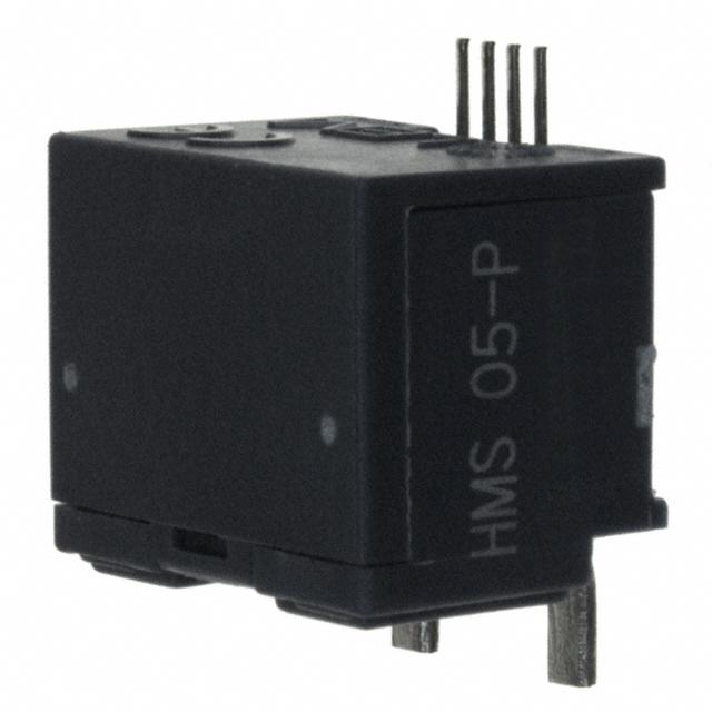
Current Transducer HMS 5..20-P
For the electronic measurement of currents: DC, AC, pulsed...,
with galvanic isolation between the primary circuit (high power) and
the secondary circuit (electronic circuit).
IPN = 5 .. 20 A
All data are given with a RL = 10 kW
Electrical data
Primary nominal
current rms
IPN (A)
5
10
15
20
VOUT
GTH
VREF
RL
ROUT
CL
VC
IC
Primary current
measuring range
IPM (A)
± 15
± 30
± 45
± 60
Primary Conductor
Size x Turns
(mm)
0.65 x 1.6 x 4T
0.65 x 1.6 x 4T
1.2 x 2.2 x 2T
1.2 x 2.2 x 2T
Type
Features
HMS 05-P
HMS 10-P
HMS 15-P
HMS 20-P
Output voltage (Analog) @ IP
VOE ± (0.625·IP/IPN) V
Theoretical sensitivity
0.625
V/IPN
Reference voltage 1) - Output voltage
2.5 ± 0.025
V
VREF Output impedance
typ. 200
W
VREF Load impedance
≥ 200
kW
Load resistance
≥ 2
kW
Output internal resistance
< 5
W
Capacitive loading
= 4.7
nF
Supply voltage (± 5 %) 3)
5
V
Current consumption @ VC = 5 V
19
mA
Accuracy - Dynamic performance data
X
Accuracy 2) @ IPN , TA = 25°C
Linearity
error 0 .. IPN
L
.. 3 x IPN
TCVOUT Temperature coefficient of VOUT @ IP = 0
TCVREF Temperature coefficient of VREF (25 .. 85 °C)
(-40 .. 25 °C)
TCVOUT/VREF Temperature coefficient of VOUT/ VREF @ IP = 0
TCG Temperature coefficient of G
VOE Electrical offset voltage @ IP = 0, TA = 25℃
VOM Magnetic offset voltage @ IP = 0,
after an overload of 3 x IPN DC
tra
Reaction time @ 10 % of IPN
tr
Response time to 90 % of IPN step
di/dt di/dt accurately followed
Vno
Output voltage noise (DC .. 10kHz)
(DC .. 1MHz)
BW
Frequency bandwidth (- 3 dB) 4)
e
≤ ± 1
≤ ± 0.5
≤ ± 1
≤ ± 0.4
≤ ± 0.01
≤ ± 0.015
≤ ± 0.2
% of IPN
% of IPN
% of IPN
mV/K
%/K
%/K
mV/K
≤ ± 0.07 % of reading/K
VREF ± 0.025
< ± 1.2
< 3
< 5
> 50
< 20
< 40
DC .. 50
V
% of IPN
µs
µs
A/µs
mVpp
mVpp
kHz
●● Hall effect measuring principle
●● Galvanic isolation between
primary and secondary circuit
●● Isolation test voltage 4300V
●● Low power consumption
●● Extremely low profile, 12mm
●● Single power supply +5V
●● Fixed offset & gain
●● For SMT mounting
Advantages
●● Small size and space saving
●● Only one design for wide primary
current range
●● High immunity to external
interference.
●● VREF pin with REF OUT & REF IN
modes
Applications
●● AC variable speed drives
●● Static converters for DC motor
drives
●● Battery supplied applications
●● Uninterruptible Power Supplies
(UPS)
●● Switched Mode Power Supplies
(SMPS)
●● Power supplies for welding
applications.
Application domain
●● Industrial
Notes : 1) It is possible to overdrive VREF with an external reference voltage
between 1.5V - 2.8V providing its ability to sink or source approximately
5 mA.
2) Excluding offset and hysteresis.
3) Maximum supply voltage (not operating) < 6.5 V
4) Small signal only to avoid excessive heatings of the magnetic core.
110512/13
LEM reserves the right to carry out modifications on its transducers, in order to improve them, without prior notice.
Page 1/6
www.lem.com
�Current Transducer HMS 5..20-P
General data
TA
TS
m
Ambient operating temperature
Ambient storage temperature
Mass
UL94 Classification
Standard
- 40 .. + 85
°C
- 40 .. + 85
°C
app. 6
g
V0
EN 50178: 1997
Isolation characteristics
Vb
Rated isolation voltage rms
with IEC EN 50178, 61010-1 standards and following conditions
categoly
Ⅲ
Over voltage
- Over voltage
category III
Pollution
degree
2
- Pollution degree 2
Heterogeneous field
- Heterogeneous field
EN50178
IEC61010-1
Single isolation
1000V
1000V
Reinforced insulation
600V
300V
Vd
dCp
dCl
CTI
Ve
Vw
Rms voltage for AC isolation test, 50 Hz, 1 min
Creepage distance
Clearance distance
Comparative tracking index (Group I )
Partial discharge extinction voltage rms @ 10 pC
Impulse withstand voltage 1.2/50 µs
4.3
> 9.4
> 9.4
> 600
> 750
8
kV
mm
mm
V
V
kV
Safety
This transducer must be used in electric/electronic equipment with respect
to applicable standards and safety requirements in accordance with the
manufacturer’s operating instructions.
Caution, risk of electrical shock
When operating the transducer, certain parts of the module can carry hazardous
voltage (eg. primary busbar, power supply).
Ignoring this warning can lead to injury and/or cause serious damage.
This transducer is a built-in device, whose conducting parts must be inaccessible
after installation.
A protective housing or additional shield could be used.
Main supply must be able to be disconnected.
Page 2/6
110512/13
LEM reserves the right to carry out modifications on its transducers, in order to improve them, without prior notice.
www.lem.com
�Dimensions HMS 5..20-P (in mm. 1 mm = 0.0394 inch)
Dimensions HMS 5..20-P (in mm. 1 mm = 0.0394 inch)
Dimensions HMS 5..20-P (in mm. 1 mm = 0.0394 inch)
Recommended connection circuit
Operation Principle
(1)
0V
(2)
HMS 05-P
47nF
47nF
Vout
5V (3)
Output
(1)
V Ref.
0V (4)
IN/OUT
(2)
Output
(3)
V Ref.
IN/OUT
(4)
4.7nF
47nF
Mechanical characteristics
• General tolerance
(unless otherwise stated)
± 0.2 mm
Dimension does not include deformation such as warp.
Mechanical
characteristics
Mechanical
characteristics
Remarks
●● General
tolerance
• General tolerance
(unless otherwise stated)
± 0.5 mm
(unless
stated)
± 0.25 mm
• VOUT otherwise
is positive when
IP flows from terminal
(IN) to
terminal 6 (OUT).
Dimensions
dodoes
not of
include
deformation
such
as not
warp
• Temperature
the primary
conductors
should
Dimension
not
include
deformation
such
as warp.
age. exceed 100°C.
080908/4
Remarks
Remarks
080908/4
(*)
+Vc
Vout
HMS 05-P
HMS 10-P
HMS 15-P
HMS 20-P
A
B
TURNS
0.65 t
1.6 w
4t
1.2 t
2.2 w
2t
Vref.(IN/OUT)
0V
A
B
TURNS
0.65 t
1.6 w
4t
1.2 t
2.2 w
2t
Pe ak 25 0deg (5 s ec m ax. ) (*)
245 +/- 5deg
2 to 5 deg /s ec
Solder
reflow
patterns
Solder reflow
patterns
6 0 + /-15sec
180 +/-3 0s ec.
150deg
P b-free reflow profile
4 to 8 d eg/s e c
180d eg
2 t o 5 deg/ sec
10 s ec m ax. ) (*)
2600deg (5
Pe ak 25
245 +/- 5deg
Tim2e to 5 deg /s ec
preliminary. will be 260 deg (5 sec max.) in final version.
6 0 + /-15sec
Page 3/4
180 +/-3 0s ec.
LEM reserves the right to carry out modifications on its transducers, in order to improve them, without prior notice.
●● VOUT is positive when IP flows from terminal 5 (IN) to
terminal
(OUT). when IP flows from terminal 5 (IN) to
• VOUT is6positive
●● Temperature
the primary conductor should not exceed
terminal 6 of
(OUT).
100°C.
• Temperature of the primary conductors should not
exceed 100°C.
110512/13
Vref.(IN/OUT)
0V
HMS 05-P
Solder reflow patterns
HMS 10-P
P b-free reflow profile
HMS 15-P
HMS 20-P
The parts and P.C.B. surface temperature
4.7nF
Operation Principle +Vc
The parts and P.C.B. surface temperature
5V
Recommended
connection
circuit
HMS 05-P
47nF
150deg
www.lem.com
180d eg
4 to 8 d eg/s e c
2 t o 5 deg/ sec
Tim e
(*)
preliminary. will be 260 deg (5 sec max.) in final version.
LEM reserves the right to carry out modifications on its transducers, in order to improve them, without prior notice.
LEM reserves the right to carry out modifications on its transducers, in order to improve them, without prior notice.
Page 3/6
Page 3/4
www.lem.com
www.lem.com
�Current Transducer HMS 5..20-P
Handling Instructions
Notes for Storage, Handling and Mounting the transducer
Storage
(1) General storage conditions: Temperature 5 .. 30 °C Humidity 40 .. 60 %RH without dew condensation
(2) Storage period:
Storage period is within 1 year after production date in general storage conditions with dry pack dessicant.
According to MSL1 (Moisture Sensitivity Level 1) requirement.
(3) Containers must prevent electric static charge build up.
Note. For over storage periods of 1 year, the customer shall confirm the solderability of the part.
Handling and Mounting
(1) Do not expose the transducer to shock or vibration.
Damage caused by shock or vibration can lead to a failure of the transducer.
(2) Do not wash the transducer.
The HMS is a non-sealed type transducer. If liquids reach inside the transducer, it will cause migration or corrosion, which will
influence the performance.
(3) Thickness of the PCB should be more than 1.5 mm.
If the thickness is not enough, the PCB tends to warp. It makes excessive tension on the transducer, which will influence the
dynamic characteristics.
(4) Be aware of the chucking force when mounting the transducer.
When you use a machine for mounting the HMS transducer, make sure the chucking force is not too much because
excessive force could cause damage to the parts inside the case, which will influence the dynamic characteristics of the
transducer. Chucking force should not exceed 3 times the weight of the transducer.
(5) Do not touch the lead pins with bare hands after they are taken out of the reel.
Lead pins of HMS are Pb free parts. If the pins are touched by bare hands, they will oxidize faster, and that could cause
soldering problems.
Do not use HMS transducer other than measuring current.
Page 4/6
110512/13
LEM reserves the right to carry out modifications on its transducers, in order to improve them, without prior notice.
www.lem.com
�This Specification is according to JIS C 0806-3, EIA-481-D
28±0.1
(more than 2000mm)
Page 5/6
110512/13
LEM reserves the right to carry out modifications on its transducers, in order to improve them, without prior notice.
www.lem.com
�Page 6/6
110512/13
LEM reserves the right to carry out modifications on its transducers, in order to improve them, without prior notice.
www.lem.com
�
很抱歉,暂时无法提供与“HMS 05-P”相匹配的价格&库存,您可以联系我们找货
免费人工找货